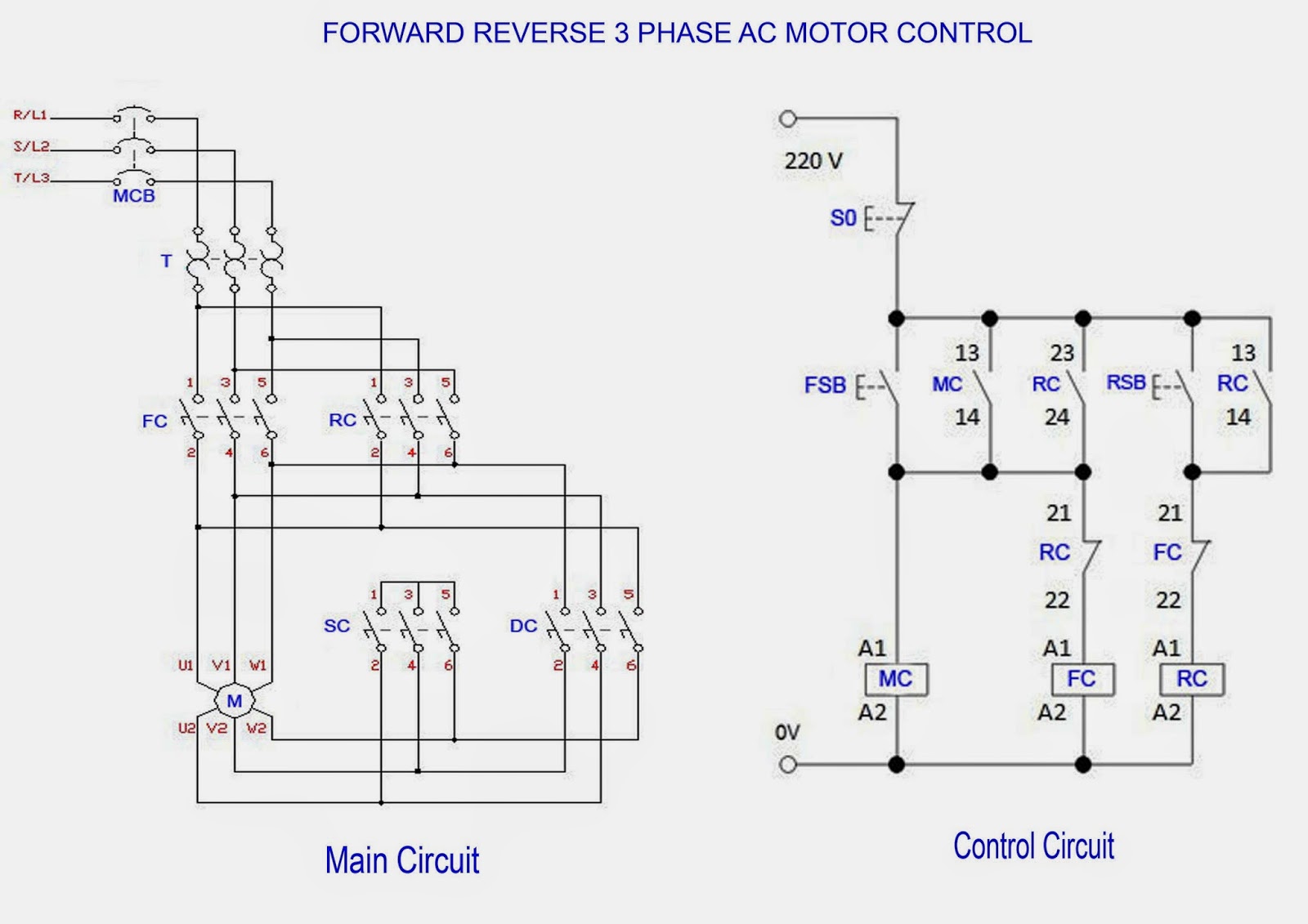
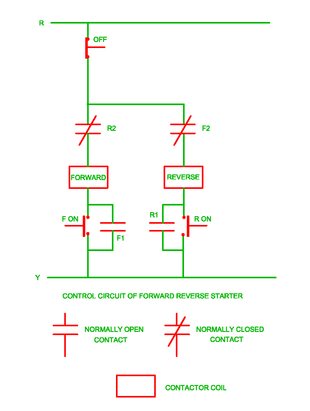
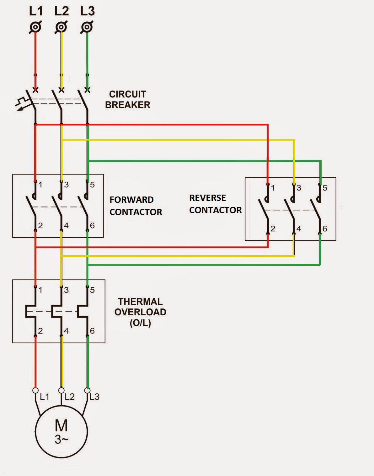
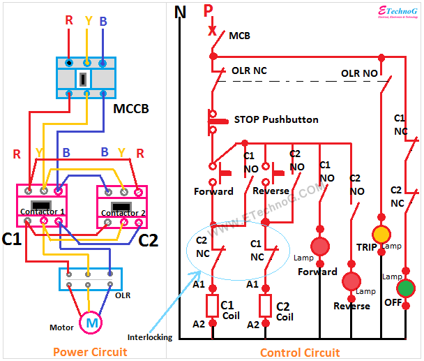
Forward reverse motor phase diagram circuit control ac electrical Electrical standards: overload relay working principle and features of Reverse forward
Electrical Standards: Overload relay working principle and features of
Motor control circuit forward reverse Forward reverse circuit control starter motor phase electrical contact working nc Figure 2-45.--schematic wiring diagram of an ac reverse-power relay.
Limit switches motor two circuit reverse dpdt forward relays wire dc control direction relay add using hook down course gif
Polarity reversing switch wiring diagramReverse power relay t2000 for generator protection Motor wiring dc 12v spdt two relays reverse diagram polarity diode forwards operate back kept blowing switchT2000 relay reverse power protection selco generator circuit control relays.
Homebuilt rovsWiring two spdt relays to operate a 12v dc motor forwards and back Electrical revolutionForward & reverse 3 phase ac motor control circuit diagram.

Polarity reversing dpdt actuator
Figure 3-113. reverse power relay test circuitRelay diagram wiring contactor reverse phase overload start circuit stop forward motor ac power starter wire direct dol control magnetic Power reverse relay circuit test tm figure 35c2 force army air.
.


Forward & Reverse 3 Phase AC Motor Control Circuit Diagram

Electrical Revolution

Electrical Standards: Overload relay working principle and features of

Figure 2-45.--Schematic wiring diagram of an ac reverse-power relay.

polarity reversing switch wiring diagram - Wiring Diagram

Figure 3-113. Reverse Power Relay Test Circuit

wiring two SPDT relays to operate a 12v DC motor Forwards and Back

Motor Control Circuit Forward Reverse | Wiring and Connection - ETechnoG