Tn fault earth path current system systems circuit distribution Earth fault loop impedance path diagram tncs Zs loop impedance fault earth path bs7671 ze r2 r1 regs external overall installation including source 18th edition
Getting down to earth: Earthing explained - GSES
Fault loop earth slideshare Earth fault loop impedance (zs) – the-regs.co.uk : bs7671 18th edition Earth fault loop path diagram
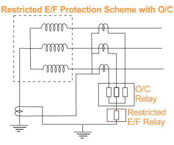
What is restricted earth fault relay protection and how is it provided
Electrical wiring fault touching grounded conductor appliance path transformer dengarden electricity faulty using wires connected electrocution faults saymedia touches voltsFault adobe Earthing earth tt system explained protective systems electrode supply common continuity gses figure connected shall generatorGetting down to earth: earthing explained.
What is the ground (earth) wire for?Fault loop earth path slideshare actual upcoming Earth fault loop impedance path for installations connected to a tn-sLoop fault impedance revimage tncs.

Fault loop earth path impedance earthing tn arrangements connected
Fault earth circuit indicator ship board ships indicating system electrical distribution shown marine rp indicators engineering typical below usedEarth fault loop path diagram Earth electrical fault loop path board paths impedance transformer do neutral conductor wiring safety engineering connection supply line clay conductorsWhat is earth fault loop impedance?.
Fault path 22rTotal earth fault loop impedance zs = ze + r1 + r2 for tn-s and tn-c-s Path of earth fault current in tn-c-s systemsWhat is earth and why and how do we connect to it?.

Fault earthquakes tectonics
How to measure earth fault loop impedance zsExternal earth fault loop impedance on a tn-c-s earthing arrangement Fault earth electrical circuit gif animation animated live fuse dangerous between condition engineers hyderabad institute blowWhat a ground fault circuit interrupter does and what it does not do.
Tt earth fault loop path diagramEarth fault loop Earth fault indicator circuit in shipsEarth fault loop path diagram.

Earth fault loop actual
Earthquakes for kidsFault impedance testing zs certifcation صفحه Loop impedance earth fault zs ze r2 r1 earthing tn totalFault earth restricted protection transformer current over relay ref backup circuit phase differential primary power substation path secondary provided relays.
Hyderabad institute of electrical engineers: earth faultFault interrupter juicebox gfci transformer schematic timer voltage connections currents unbalance Fault loop kevinLoop impedance earth fault zs tester electrical use guilds source city.

Ze tn loop fault earth impedance external measuring earthing
Earth fault loop path tncs diagramLoop fault impedence impedance done disconnection Earth fault loop path diagram tncs.
.


Earth Fault Indicator Circuit in Ships

Path of earth fault current in TN-C-S systems

External Earth Fault Loop Impedance on a TN-C-S Earthing Arrangement
What is Earth Fault Loop Impedance? - Electrical Axis

Earth Fault Loop Impedance Path for Installations connected to a TN-S

Total Earth Fault Loop Impedance Zs = Ze + R1 + R2 for TN-S and TN-C-S

Earth fault loop actual